PWM SOLAR CHARGE CONTROLLER CIRCUIT DIAGRAM
This post explain about the working of pulse width modulation solar charge controller along with inverter control.


INPUT PROTECTION
: Built in
Blocking Diode to prevent SPV array from reverse polarity
and
to prevent reverse flow of current from Battery
(SPV SIDE) - Built-in
MOV protection against
HIGH VOLTAGE LIGHTNING during rainy season
CHARGING : MOSFET Based PWM Charging (microcontroller controlled)
- BOOST CHARGING
till the battery
voltage reached
14.5V
- ABSORPTION MODE to charge the battery
for 100% energy storage
- CHG. ON when PV Volt goes up 10V-11V
CHARGING LED : - LED Flash during boost nad LED constant during absorption
- LED OFF when charging
is OFF or PV Volt below 10V
LOAD CONTROL : - LOAD connector
continous active in NORMAL during Day or Night
- LOAD OFF during lo-batt
cut-off at 9.5V or 10V
- LOAD reconnect
when battery voltage goes up 12.5V or above
CIRCUITRY : - Microcontroller based electronics
- MOSFET based load control
switch and charging
switch
- PWM charging for 100% energy storage compare to ON / OFF type charge controller

working of Pwm solar charge controller :
This is a PIC16f72 microcontroller based Solar Charge Controller with two steps charging algorithm.
a) When the battery is < 14.2V, the circuit start charging the battery in Boost Mode with full current
from the Solar Panel.
b) When the battery voltage Reached to 14.5V the circuit charge the battery Trickle mode, in this
mode the circuit maintaintain the Battery voltage @14.5V untill the panel provide the enough
voltage from Sun.
Now let us discuss about the circuit operation. The whole control circuit is powered from battery bank
(12V to 48V).
Battery is connected through a Fuse of rated capacity for protecting the circuit from reverse polarity, a
diode D4 is used for that whenthe battery is reverse connected the diode D4 conduct and Fuse
blown.
A series pass regulator is comprising Q3, R3 and D2 used to get 12V DC from Battery (when battery
bank is 24V or 48V), 12V is used to power the Inverter control Relay and PWM Switch (Q6 and Q8). A 5V regulator comprising RG1 is used to power the microcontroller.
Here the heart of the circuit is U1 PIC16f72 8-bit microcontroller. As about its architecture and pin
detais refer to its Data sheet .
U1 is clocked with an external crystal oscillator X1 (4Mhz), C11 and C12. Pin1 of U1 is for power on
reset, pin 25 to pin 28 (Port RB4 - RB7) are for LEDs (Relay on, Lo-Batt, Chg. status, PV ON).
Pin 12 (Portc1) is used to power On / Off the inverter control Relay. Pin 20 of U1 is VDD pin and 5V is
fed to this pin from RG1 (7805), Pin 19 is ground.
Now let us discuss about the charging algorithm and working of it.
Q1 and Q2 a n-channel MOSFET is used as a charging switch, DC voltage from panel is fed to this
MOSFET switch through a Schottky doide D1, this diode is used so that the battery voltage should
not pass to panel in night time.
When the battery voltage is less than 14.2 V, the Mosfet Q1 and Q2 is fully ON, and Full current from
panel is fed to battery through D1 and Q1, this is called BOOST mode, and in this mode Chg Led is
flashing.
Q1 and Q2 are connected in the high side of the supply line and its source pi is floating, so to switch
ON the Mosfet Q1/Q2 its gate pin require the double voltage of Vcc so that the voltage across its gate
and source pin should be equal to Vdd.
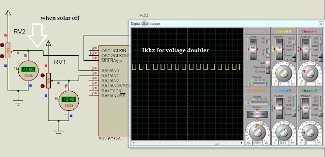
Here a voltage doubler circuit is incorporated using D5, D8, Q4, Q5 and Q7. a 1kHz squarewave
pulse is generated from pin 14 of U1 and is further fed to Q7 and Coplimentary totem pole pair (Q4 /
Q5). These Q4 / Q5 are used to charge and discharge C9 through D5 and D6, hence the voltage
across the capacitor C20 is almost double of Vdd. This voltage is used to switch ON the MOSFET
Q1.


Now let us discuss about the PWM control of the circuit. the microcontroller intially switch ON the
MOSFET Q1 fully to pass the full current on to the battery, and simutaneously sense the battery
voltage at its pin 3, as soon as the battery voltage reaches to 14.2V absortion mode starts working.
Pin 13 of Microcontroller is proving the PWM pulse and controlling the duty cycle of ON and OFF
time of Q1 so that the controller maintain the battery voltage @14.2V and to keep the charging in
Absorption mode.


Intially when the charger is ON the pin13 of controller increases its duty cycle with a small time delay
from 0% to 100% duty cycle, which in result a delay charging current increase. When the output from
pin13 of U1 is 100% dutycycle, then transistor Q8 is On and which in turn makes OFF Q8, and hence
the MOSFET Q1 is fully ON.
Simultaneously the microcontroller senses the battery voltage at its pin3, when the battery voltage is
>14.2V the the PWM starts decreasing its output untill the battery voltage is equal to 14.2V.
Relay:
Here a relay is provided for user if they want to switch OFF the mains and run the inverter through
battery, which in turn to save the electricity.
the relay becomes ON when the battery voltage goes above 14.5V and becomes OFF when battery
voltage goes below 11V.
BOM :

PCB & Wiring :

INDUUCTOR DATA:
20AMP :
15-TURN (17SWG)
T-27 TOROIDAL
10AMP :
20-TURN (18SWG)
T-22 TOROIDAL
30AMP :
10-TURN (16SWG)
T-30 TOROIDAL
Testing:
1) Do not connect solar panel initially, microcontroller (U1), connect DC power supply with current set at
max 1-amp, coonect it to the battery terminal, and switch ON the supply,
2) measure voltage at emitter of Q3 it is 11.6V, pin3 og RG1 it is 5v DC, pin1 of U1 it is 5V, pin20 of U1 it
is 5V, pin 19 of U1 it is 0V.
3)switch OFF the supply connect U1 on its base, switch ON the supply check squarewave at pin14 of
U1,if its coming check voltage atacross C10, it is almost double the battery voltage. If the squarewave is
not coming from Pin14 of U1 the replace the U1, if the squarewave is there but the voltage across C10
is equal to battery voltage then check Q7, Q5, Q4, D5 and D6.
4) Now remove DC power supply from battery connector and connect it to PV connector and connect
battery to battery terminal, switch ON the power supply and increase the power supply voltage from to
10V, At 10V or above the charging LED starts blinking and PWM pulse from pin13 of U1 start increasing.
You can purchase hex code and pcb layout for 25 usd , for source code contact sandysplash230@gmail.com
hi nice post what is load 1 2 3?
ReplyDeletethose are dc loads you can use it for a dc loads like a dc light,fan etc..
ReplyDeletehi sandeep
ReplyDeletewhy that inductor is used their?
hi....it is used for step down the solar panel voltage ..
ReplyDeleteis this mppt ?
ReplyDeleteno its pwm
ReplyDeletedear sir,
ReplyDeleteDo you offer technology transfer for PWM SOLAR CHARGE CONTROLLER CIRCUIT DIAGRAM?
hi there
ReplyDeletecan i have its proteus file
if you can provide me it will be great help for me
khalidmalik.iqbal@gmail.com
hi there
ReplyDeletecan i have its proteus file
if you can provide me it will be great help for me
khalidmalik.iqbal@gmail.com
hi dear
ReplyDeletewill you please provide me its proteus file for academic purpose
sorry i dont have proteus
DeleteHi plus can u help me with the code and ask files?
DeleteI dont think that he will reply you......
ReplyDeleteI dont think that he will reply you......
ReplyDeletehi sandeep I need to buy this project with all the details and specifications. how much does it cost. please do mail to deend.dayal.01.dd@gmail.com
ReplyDeleteHi I need to know what is the cost of the hex file for this project
ReplyDeletesir will u pls send me the full pin specifications and power ratings of the circuit and the program of this circuit
ReplyDeletehi sandeep will you provide me the program for this project
ReplyDeletehi sandeep will you please provide me the program for this project this is naveen from banglore
ReplyDeletemy mail id is 290naveen295@gmail.com
WILL YOU PLEASE SEND FULL PROJECT TO MY MAIL ID
ReplyDelete290NAVEEN295@GMAIL.COM
dear sandeep kumar will you pleas send me the full specifications of the circuit
ReplyDeleteto 290naveen295@gmail.com
full specifications
ReplyDeletexxxxxxxxxxxxxxxxxxxxxxxxxxxxxxxxxx
ReplyDeleteWhy u use Fuse in parallel with blocking diode???
ReplyDeleteHow can u use the Buck-converter to charge 14V battery with 12V Panel?????
ReplyDeleteHow Buck Converter can be used to charge 14 V battery with 12 V panel?????
ReplyDeleteDear sandeep kumar dada,
ReplyDeletepls give me total circuit diagram with code
please i need it too tweakman1@yahoo.com
ReplyDeleteHI
ReplyDeletehi
ReplyDeletei try to download the file but cannot. pls if can, send it to my email:
a.a.khalifa.1992@hotmail.com
i really want to understand more about the circuit
thanks
hello
ReplyDeletecan i have the code, because i cannot download it.
this is my email:
a.a.khalifa.1992@hotmail.com
Can you provide hex file !!!
ReplyDeletethe pwm charger circuit and code is error, can you give me a charger circuit and PWM Code on email: tienviengl@gmail.com. thanks you so much
ReplyDeletehi, i am unable to get the code. there is error 400 whenever i click on the source code link
ReplyDeletehello i am antony from ghana, paid for this project.please forward me files.
ReplyDeleteplease check your email .i have sent.
Deletethx very much .
Deletethis is working fine. i need a modification in it , instead of absorbtion charging can you make it as float charg by reducing the current to 1amp when the battery is full ?
is this possible ?
Can this project be adpted/modified for a 24V System
ReplyDeleteGreetings, I'm Sam from Brazil and i would like to purchase this, although i have some questions. Is the original code in C going to come along the .Hex file? By paying 25usd i'll be buying the first or the second circuit?, becase i intend to purchase the first circuit.
ReplyDeleteplease send your whatsaap number to email sandysplash230@gmail.com for fast communication
Delete